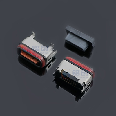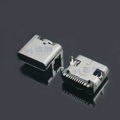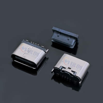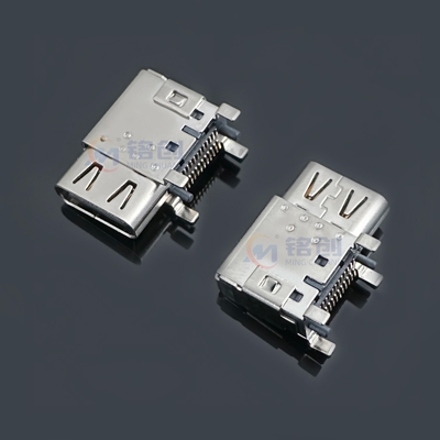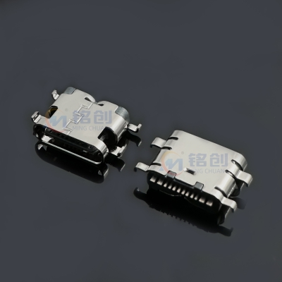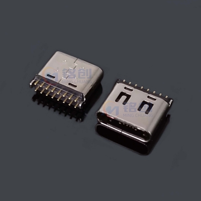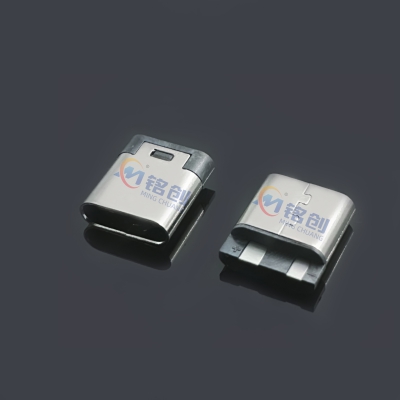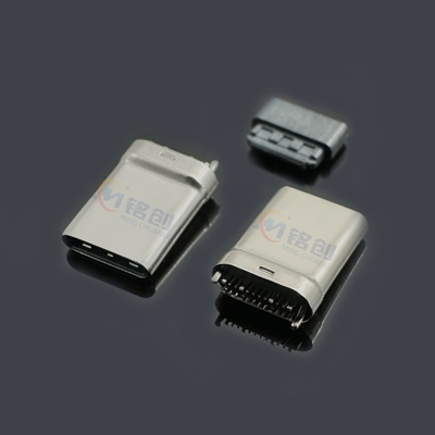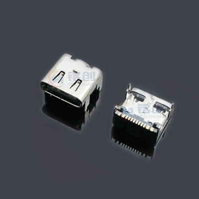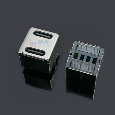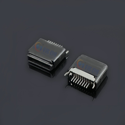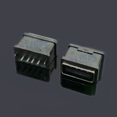
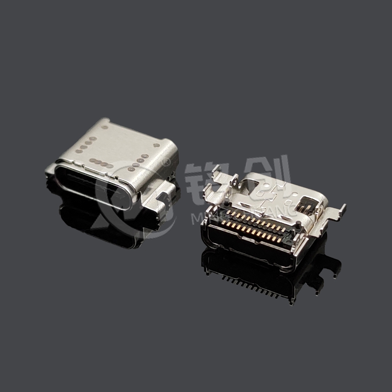
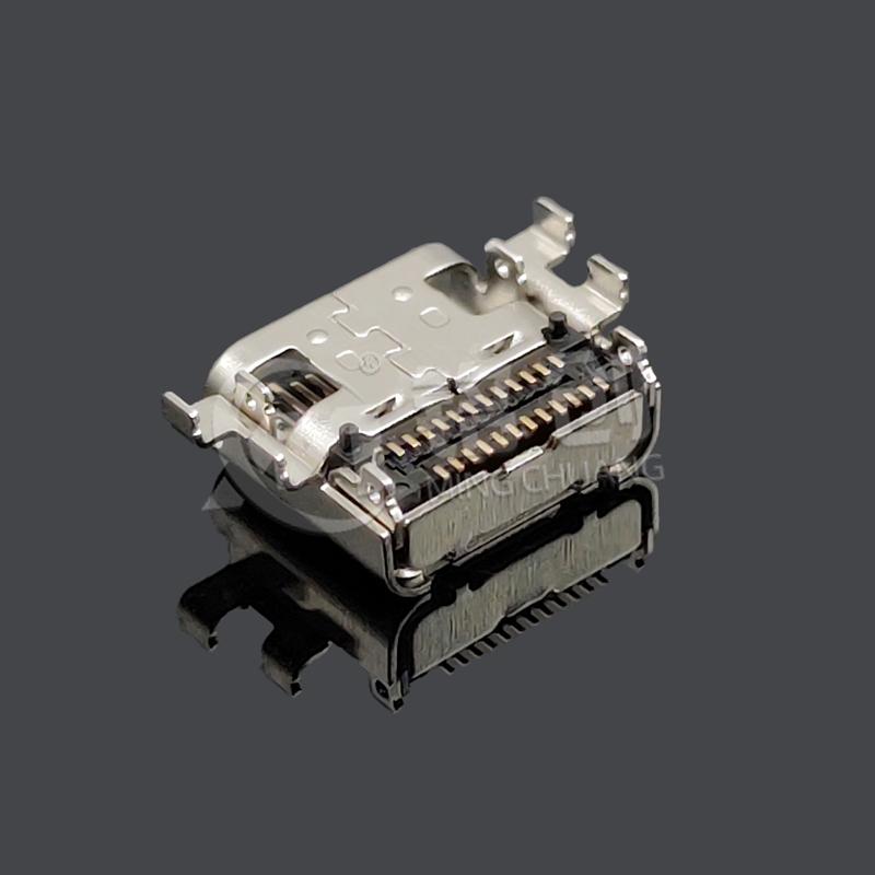
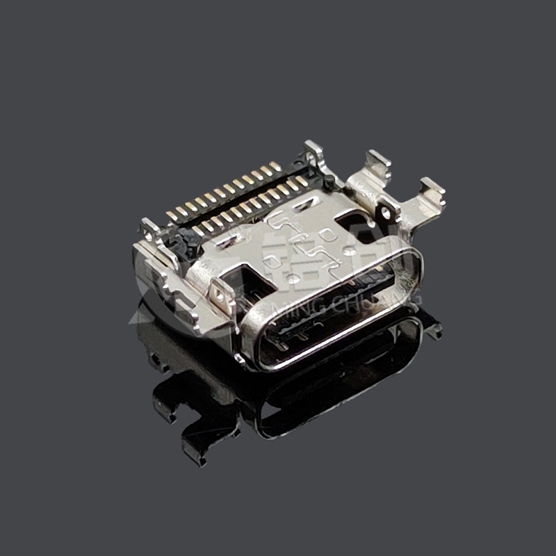

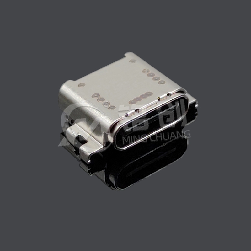


TYPE C female seat 24PIN board with double SMT and back cover, double shell with DIP pins CH=1.58 L=8.25, shell pin length 0.6 USB4.0 is a fully functional connector designed for high-speed transmission and high reliability scenarios. The 24PIN pin covers all channels of USB 4.0 protocol and supports 40Gbps ultra high speed data transmission and PD fast charging; The dual SMT+DIP foot composite fixed structure on the board enhances installation stability, and the dual shell (metal front shell+LCP back cover) design improves protection and shielding performance; CH=1.58mm ultra-thin height suitable for compact devices, L=8.25mm length saves space, widely used in high-end laptops, docking stations, industrial cameras, medical equipment and other scenarios that require high-speed data and stable power supply.


Interface and protocol compliance: Fully compliant with the USB4.0 specification (Revision 1.0) and PD 3.1 standard published by the USB Implementers Forum (USB-IF), certified by USB-IF TID (number available), ensuring compatibility with USB4.0 male and Thunderbolt 4 devices, avoiding transmission interruptions and fast charging failures caused by protocol incompatibility.
Environmental compliance: Fully compliant with EU RoHS 3.0 (2015/863/EU) and Chinese GB/T 26572-2011, strictly restricting 10 harmful substances such as lead, mercury, cadmium, etc. All raw materials (metals, LCP, coatings) have passed SGS environmental testing and provided compliance reports.
Electrical safety compliance: comply with IEC 62368-1 "Safety Standard for Audio, Video and Information Technology Equipment", with insulation resistance ≥ 1000M Ω (500V DC) and withstand voltage ≥ 1000V AC (no breakdown for 1 minute); Electromagnetic compatibility meets FCC Part 15 Class B (radiation ≤ 40dB μ V/m @ 1GHz) to avoid interference with peripheral devices.
Production quality compliance: Following the ISO 9001 quality management system, full process testing (raw material conductivity, dimensional accuracy, finished product signal integrity) is carried out, with 1000pcs sampled from each batch and a non conformance rate of ≤ 0.1%. Batch quality reports can be provided.
For more information, please contact us:
- Hotline: +86 13310802726
- Email: mc13310802726@163.com
Storage and transportation
Storage environment: Temperature -10 ℃~40 ℃, relative humidity 30%~60%, avoid high temperature and humidity, direct sunlight or contact with corrosive gases (such as solder fumes), prevent terminal oxidation and aging of LCP back cover.
Transportation requirements: Anti static shielding bag+tray packaging, built-in moisture-proof agent, labeled "Handle with care" and "Anti static" to avoid violent handling that may cause deformation of the shell and bending of the DIP feet.
After opening: Unused products must be resealed within 24 hours and exposed to air for no more than 48 hours to prevent dust from adhering and affecting welding.
Installation operation
PCB design: The solder pads need to match the pin size (signal pin spacing 0.5mm, DIP pin aperture 0.7mm ± 0.05mm); The high-speed differential line needs to control an impedance of 100 Ω, with a line length matching error of ≤ 50mil, and avoid 90 ° corners.
Reflow soldering parameters: preheating section of 150-180 ℃ (60 seconds), peak section of 260-265 ℃ (≤ 8 seconds), cooling rate of ≤ 3 ℃/second, to prevent deformation of LCP back cover and terminal detachment caused by high temperature.
Testing requirements: After installation, AOI+X-ray testing should be conducted to confirm that there is no virtual soldering or continuous soldering, the DIP pin insertion depth should be ≥ 0.4mm, and the female seat tilt angle should be ≤ 1 °.
Operation and Maintenance
Current limit: VBUS power supply should not exceed 5A (at 28V) to avoid long-term overload and terminal overheating and burnout.
Insertion and unplugging specifications: Vertical insertion and unplugging are prohibited, and tilting or rotating force is prohibited to prevent terminal wear and shell deformation (it is recommended to control the insertion and unplugging life within 10000 times).
Cleaning and maintenance: When there is dust on the interface, use a dry soft bristled brush to clean it. Do not touch the terminals with metal tools to prevent scratching the coating.
For more information, please contact us:
- Hotline: +86 13310802726
- Email: mc13310802726@163.com


|
Mob:13310802726 / Tel:0769-85605360 |

|
Email:mc13310802726@163.com |

|
Address: No. 1, Chengxin Road, Changan Town, Dongguan City, Guangdong Province, China |

Copyright © 2024-2026 Mingchuang Technology (Dongguan) Co., Ltd. All rights reserved Web Design—Quanfang Network